 ingredientpharm
Abstract
This case study is a short abstract on spouted bed characteristics, following closely findings in the publication by J. Vanamu and A. Sahoo [1].
Spouted bed systems are of highest importance for all powder processing industries, and more specific in pharmaceutical industry for coating and drying in pellet technologies [2]. These systems offer manufacturing particularly fine and temperature-sensitive particles from small to large scale: laboratory systems are capable of processing product volumes of very few grams, while production systems can handle capacities of several tons [3].
But how to control conditions in spouted beds for efficient process applications, like mixing, coating, or drying?
There might be certain reasons, that the hydrodynamic behavior of the spouted bed in the pharmaceutical industries is less investigated. The referred publication shed some light on the hydrodynamic characteristics of a spouted bed where the MCC Spheres (CELLETS®) are adopted as the bed material. These starter cores are ideal model systems due to their perfect sphericity and zero-level friability. At the same time, smooth and defined surface structure initiate perfect modelling conditions in the spouted bed dynamics.
Material
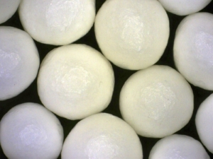
CELLETS®, made of 100% Microcrystalline Cellulose, have been used as bed material. The physical properties of the CELLETS® are shown in Table 1. The CELLETS® particle morphology is represented in Figure 1.
| Parameter | Value |
| CELLETS® 700 and CELLETS® 1000 | |
| Size distribution | 700-1000 µm (CELLETS® 700)
1000-1400 µm (CELLETS® 1000) |
| Bulk density | 800 kg/m3 |
| Particle sphericity | > 0.9 |
| Void fraction | 0.42 |
| Geldart classification | B |
Table 1: Physical properties of the CELLETS®.
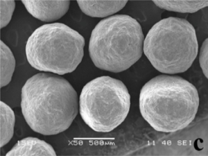
Figure 1: SEM micrographs of CELLETS® 700, found in [1].
Spouted bed: experiment setup
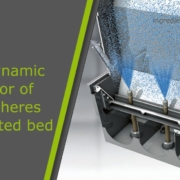
There are some international players on the market of spouted bed technologies, such as Glatt which seems to be the major one (Figure 2). In this framework, a self-made setup is used for experiments. The experiments that have been carried out in a column, which is fabricated from a Perspex sheet. This column consists of a cylindrical section of height 0.53 m and a diameter of the cylinder of 0.135 m. The column further converged the diameter of the cylinder to 0.05 m as a conical bottom having a length of 0.47 m. The spouting air is supplied by a compressed air line is controlled by a gas regulator. The airflow is controlled by a gate valve and a mesh plate having a mesh size less than the size of the bed material is employed as a separator preventing the backflow of the bed material. Images are captured using a high-speed video camera to gain more details of the hydrodynamic characteristics of the flow pattern inside the spouted bed geometry.
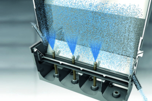
Figure 2: Scheme of a spouted bed (Glatt, Germany).
Experiments & spouted bed results
Experiments are carried out with three different static bed heights of shallow depth wherein the bed height is in the range of factor 2-3 of the Inlet diameter using two different particle distribution classes at 500-710 µm and 700-1000 µm, respectively. Analyzed parameters are the pressure drop across the bed, the bed expansion ratio, and the clusters concerning the superficial gas velocity are focused in the following.
J. Vanamu et al. found that the “bed expansion ratio increases with increasing superficial gas velocity until the onset of external spouting, further increase in the superficial gas velocity, the bed expansion ratio decreases. With increasing the volume of bed, the bed expansion ratio decreases. In a larger volume of bed, the particles tend to spout into the freeboard region rather than expanding with higher superficial gas velocity”. Initial spouting is symmetric, but with increasing superficial gas velocity spouting becomes asymmetric, and asymmetry is more pronounced or starts at lower superficial gas velocities for smaller particles. This agrees with existing theories of hydrodynamic behavior in a fluidized environment. Respecting the necessarity of a proper flow behavior for mixing, coating or drying applications in drug processing, symmetric spouting is essential. In turn, the superficial gas velocity may be kept low.
In case that high superficial gas velocity regimes are required for the operations a draft tube may be installed within the column to achieve the symmetric spout formation.
Summary
This case study highlights the Hydrodynamic behavior of MCC spheres in a spouted bed using image processing method. MCC spheres in the range between 500-710 µm and 700-1000 µm had been employed. All spheres showed a symmetric and asymmetric spouting in the spouted bed. With increasing superficial gas velocity, the fully suspended particles are limited to a certain height in the freeboard region due to the gas-solid crossflow. A change from symmetric to asymmetric spouting is observed with increasing superficial gas velocity.
Keeping the conditions efficient for the mixing, coating or drying applications requires finally to suppress high superficial gas velocities, or changing the setup in such way, that symmetric spouting conditions are kept upright even at higher superficial gas velocities.
References
[1] J. Vanamu and A. Sahoo, Particuology 76 (2023) 101
[2] L. A. P. de Freitas, Particuology 42 (2019) 126
[3] Glatt GmbH, Binzen, Germany. Online on Nov 8, 2022: Spouted bed systems – Glatt – Integrated Process Solutions
Great thanks to Arihant Innochem Pvt. Ltd. who supplied and donated CELLETS® for this study.
 ingredientpharm